
.pdf-1-500x450.jpg)
.pdf-206-500x450.jpg)
.pdf-363-500x450.jpg)


.pdf-1-80x80.jpg)
.pdf-206-80x80.jpg)
.pdf-363-80x80.jpg)

$25.00
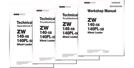
Workshop Manual
1Troubleshooting Manual
1Operational Principle Manual
1Wiring Diagram
2Illustrated factory set of Service Manuals for Hitachi Zaxis 4WD Loaders Models ZW370-6.
This manuals will assist you in diagnosing, repairing, troubleshooting, and operating for your 4wd loader or 4wd loader.
You can use a Windows, Mac, or Android device to view this manuals. You only need to have a PDF reader installed.
Covered Models:
Zaxis ZW370-6
The manual comprises 5 documents, including the Workshop Manual, Troubleshooting Manual, Operational Principle Manual, and two Wiring Diagrams
1. Workshop Manual (WNHJ40-EN-01)
Format: PDF, 869 pages
Language: English
Table of Contents:
GENERAL
Precautions for Disassembling and Assembling
Tightening
Painting
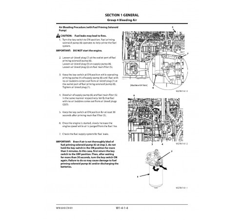
Bleeding Air
Pressure Release Procedure
Preparation
MAINTENANCE STANDARD
Body
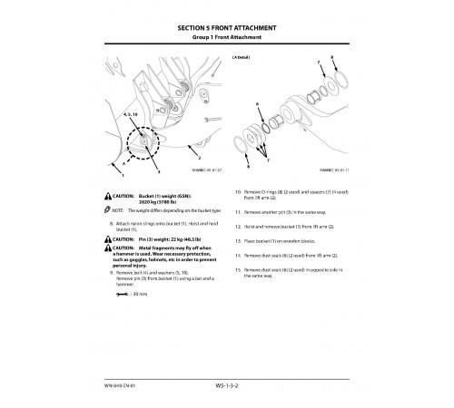
Front Attachment
BODY
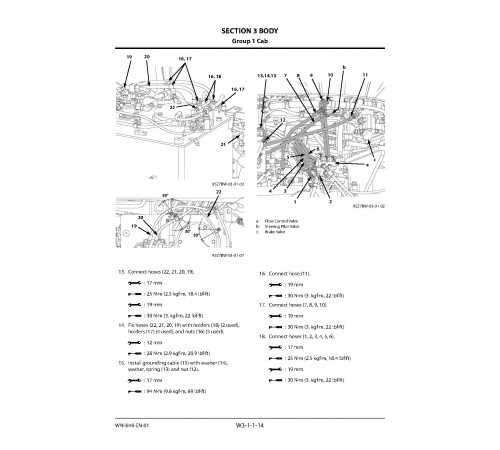
Cab
Counterweight
Center Hinge
Engine
Radiator Assembly
Hydraulic Oil Tank
Fuel Tank
Pump Device
Control Valve
Pilot Valve
Brake Charge Valve
Combination Valve
DEF Tank
Flow Regulator Valve
Cooling Fan System
Aftertreatment Device
Ride Control Valve and Accumulator
Battery Disconnect Switch
TRAVEL SYSTEM
Tire
Drive Unit
Axle
Propeller Shaft
Brake Valve
Steering Pilot Valve
Steering Valve
Steering Cylinder
Emergency Steering Device
Reducing Valve
Stop Valve
Main Pressure Block
Priority Hammer Valve and Shuttle Valve
Check Valve
Joystick Steering
Axle Oil Cooler
FRONT ATTACHMENT
Front Attachment
Cylinder
2. Troubleshooting Manual (TTNHJ40-EN-00)
Format: PDF, 540 pages
Language: English
Table of Contents:
SECTION 4 OPERATIONAL PERFORMANCE TEST
SECTION 5 TROUBLESHOOTING
INTRODUCTION
To The Reader
Additional References
Manual Composition
Trademark
Safety Alert Symbol and Headline Notations
Units Used
SYMBOL AND ABBREVIATION
SAFETY
Recognize Safety Information
Understand Signal Words
Follow Safety Instructions
Prepare for Emergencies
Wear Protective Clothing
Protect Against Noise
Inspect Machine
General Precautions for the Cab
Use Handrails and Steps
Never Ride Attachment
Adjust Operator’s Seat
Ensure Safety Before Rising from or Leaving Operator’s Seat
Fasten Your Seat Belt
Move and Operate Machine Safely
Handle Starting Aids Safely
Operate Only from Operator’s Seat
Jump Starting
Investigate Job Site Beforehand
Equipment of Head Guard, ROPS, FOPS
Provide Signals for Jobs Involving Multiple Machines
Keep Riders Off Machine
Drive Safely
Drive Machine Safely (Work Site)
Drive Safely with Bucket Loaded
Drive on Snow Safely
Travel on Public Roads Safely
Avoid Injury from Rollaway Accidents
Avoid Accidents from Backing Up and Turning
Avoid Positioning Bucket or Attachment Over Anyone
Avoid Tipping
Never Undercut a High Bank
Dig with Caution
Perform Truck Loading Safely
Avoid Power Lines
Precautions for Operation
Precautions for Lightning
Object Handling
Protect Against Flying Debris
Park Machine Safely
Store Attachments Safely
Transport Safely
Handle Fluids Safely−Avoid Fires
Practice Safe Maintenance
Warn Others of Service Work
Support Machine Properly
Stay Clear of Moving Parts
Support Maintenance Properly
Prevent Parts from Flying
Prevent Burns
Replace Rubber Hoses Periodically
Avoid High-Pressure Fluids
Prevent Fires
Evacuating in Case of Fire
Beware of Exhaust Fumes
Precautions for Welding and Grinding
Avoid Heating Near Pressurized Fluid Lines
Avoid Applying Heat to Lines Containing Flammable Fluids
Precautions for Handling Accumulator and Gas Damper
Remove Paint Before Welding or Heating
Beware of Asbestos and Silica Dust and Other Contamination
Prevent Battery Explosions
Service Air Conditioning System Safely
Handle Chemical Products Safely
Dispose of Waste Properly
Notes on Aftertreatment Device
Precautions for Communication Terminal
Precaution for Communication Terminal Equipment
Before Returning the Machine to the Customer
SECTION AND GROUP CONTENTS
SECTION 4 OPERATIONAL PERFORMANCE TEST
Group 1 Introduction
Group 2 Standard
Group 3 Engine Test
Group 4 Machine Performance Test
Group 5 Component Test
Group 6 Adjustment
SECTION 5 TROUBLESHOOTING
Group 1 Diagnosing Procedure
Group 2 Monitor
Group 3 e-Service
Group 4 Component Layout
Group 5 Troubleshooting A
Group 6 Troubleshooting B
Group 7 Air Conditioner
Group 8 Joystick Steering System
SERVICE MANUAL REVISION REQUEST FORM
The Attached Diagram List
3. Operational Principle Manual (TONHJ40-EN-01)
Format: PDF, 525 pages
Language: English
Table of Contents:
GROUP CONTENTS
Specifications
Component Layout
Component Specifications
SYSTEM
Controller
Control System
Engine System
Hydraulic System
Electrical System
COMPONENT OPERATION
Pump Device
Control Valve
Cooling Fan System
Steering Pilot Valve
Steering Valve
Pilot Valve
Charging Circuit
Drive Unit
Axle
Brake Valve
DEF Supply System
Others
SERVICE MANUAL REVISION REQUEST FORM
4. Wiring Diagram (TTNHJ40-EN-01_Circuit)
Format: PDF, 26 pages
Language: English
Table of Contents:
HYDRAULIC CIRCUIT DIAGRAM(1/2)
HYDRAULIC CIRCUIT DIAGRAM (2/2)
ELECTRICAL CONNECTION DIAGRAM (S/N 5001 to 5020,9001 to 9010) (1/4)
ELECTRICAL CONNECTION DIAGRAM (S/N 5001 to 5020,9001 to 9010) (2/4)
ELECTRICAL CONNECTION DIAGRAM (S/N 5001 to 5020,9001 to 9010) (3/4)
ELECTRICAL CONNECTION DIAGRAM (S/N 5001 to 5020,9001 to 9010) (4/4)
ELECTRICAL CONNECTION DIAGRAM (S/N 5021-,9011-) (1/4)
ELECTRICAL CONNECTION DIAGRAM (S/N 5021-,9011-) (2/4)
ELECTRICAL CONNECTION DIAGRAM (S/N 5021-,9011-) (3/4)
ELECTRICAL CONNECTION DIAGRAM (S/N 5021-,9011-) (4/4)
JOYSTICK STEERING ELECTRICAL CONNECTION DIAGRAM
FRONT CHASSIS WIRING DIAGRAM
REAR CHASSIS WIRING DIAGRAM (1/3)
REAR CHASSIS WIRING DIAGRAM (2/3)
REAR CHASSIS WIRING DIAGRAM (3/3)
FLOOR WIRING DIAGRAM (REAR CONSOLE) (1/3)
FLOOR WIRING DIAGRAM (REAR CONSOLE) (2/3)
FLOOR WIRING DIAGRAM (REAR CONSOLE) (3/3)
FLOOR WIRING DIAGRAM (SIDE CONSOLE)
FLOOR WIRING DIAGRAM (FRONT CONSOLE)
STICK STEERING WIRING DIAGRAM (ELECTRIC TYPE)
STICK STEERING WIRING DIAGRAM (ARMREST HARNESS)
STICK STEERING WIRING DIAGRAM (HYDRAULIC TYPE, W/OUT STEERING WHEEL)
CAB WIRING DIAGRAM
STICK STEERING HYDRAULIC DIAGRAM
AXLE OIL COOLER HYDRAULIC CIRCUIT DIAGRAM
5. Wiring Diagram (TTNHJ40-EN-00_Circuit)
Format: PDF, 27 pages
Language: English
Table of Contents:
HYDRAULIC CIRCUIT DIAGRAM (1/2)
HYDRAULIC CIRCUIT DIAGRAM (2/2)
ELECTRICAL CONNECTION DIAGRAM (1/4)
ELECTRICAL CONNECTION DIAGRAM (2/4)
ELECTRICAL CONNECTION DIAGRAM (3/4)
ELECTRICAL CONNECTION DIAGRAM (4/4)
FRONT CHASSIS CABLE LAYOUT AND WIRING DIAGRAM
REAR CHASSIS CABLE LAYOUT (1/3)
REAR CHASSIS CABLE LAYOUT (2/3)
REAR CHASSIS CABLE LAYOUT (3/3)
REAR CHASSIS WIRING DIAGRAM (1/3)
REAR CHASSIS WIRING DIAGRAM (2/3)
REAR CHASSIS WIRING DIAGRAM (3/3)
FLOOR CABLE LAYOUT (Rear and Side Console)
FLOOR WIRING DIAGRAM (Rear Console) (1/3)
FLOOR WIRING DIAGRAM (Rear Console) (2/3)
FLOOR WIRING DIAGRAM (Rear Console) (3/3)
FLOOR WIRING DIAGRAM (Side Console)
FLOOR CABLE LAYOUT (FRONT CONSOLE)
FLOOR WIRING DIAGRAM (Front Console)
CAB CABLE LAYOUT
CAB WIRING DIAGRAM
HYDRAULIC CIRCUIT DIAGRAM OF OPTIONAL SYSTEM
JOYSTICK STEERING ELECTRICAL CONNECTION DIAGRAM
JOYSTICK STEERING CABLE LAYOUT (Rear and Side Console) (Option)
JOYSTICK STEERING WIRING DIAGRAM (Rear and side consoles)
JOYSTICK STEERING WIRING DIAGRAM (Armrest harness)
Included
Workshop Manual
1Troubleshooting Manual
1Operational Principle Manual
1Wiring Diagram
2Reviews: 0
There are no reviews for this product.
Questions: 0
No questions about this product.
Similar products

